Intro to PLC Programming
A programmable logic controller (PLC) is an industrial computer that has been designed to fit into the control cabinet in a demanding production environment. The main features are reliability, processing fault diagnosis, and flexibility in adapting, verifying, and troubleshooting the program. The initial purpose of PLC was to provide a step forward to the existing relay logic systems used in industrial automation.
In the past, before the PLCs were invented, production lines were controlled by systems based on relay logic and contactors, which could be quite extensive and hard to troubleshoot. It means that everything was hardwired; there was no software layer on the system. It was impossible to look into the program on the computer and view the things in the programming environment.
The invention of PLCs has opened up many opportunities in the field of industrial control systems. These systems have become more advanced, now offering features like data collection and system monitoring. In the past, when everything was hardwired, modifications to the system logic required adjustments to physical cable connections. However, with the current setup, improvements to the system program logic can be directly implemented within the PLC program. The PLC, functioning as the main hardware, manages all connected elements, serving as the primary unit in the control system.
Distinguishing PLCs from Conventional Computers
The stability of PLCs over conventional computers is one of their advantages. PLCs are designed to function reliably and without interruption over long periods in the industrial environment. This reliability level is essential in operations where downtime or system failures can have serious effects. PLCs are approved for use in industrial environments through compliance with relevant international standards.
Signal Handling in PLCs
PLCs handle various types of signals, which can be categorized into three main groups:
- Physical Inputs:
- PLCs handle signals originating from physical inputs, such as buttons, sensors, and temperature gauges. Whether it’s a simple push-button command or data from a complex temperature sensor, PLCs efficiently process these physical inputs, ensuring precise control and monitoring.
- Physical Outputs:
- PLCs translate their processing into actions through physical outputs. These can include signals to control relays, contactors, actuators, motors, and valves.
- Process Variables:
- PLCs manage and interpret various process variables critical for industrial operations. These variables include status indicators, control parameters, and different states within a process. The ability of PLCs to monitor and control these variables ensures a finely tuned and responsive industrial system.
Applications in Varied Industries
Here are some examples of PLCs varied applications across many industries to demonstrate their multipurpose:
- Automotive Industry – Producing Cars:
- In the automotive sector, PLCs can control car door manufacturing lines or even the whole control assembly line. They can handle control of the valves, fixtures, drives, servos, and robots.
- Warehousing – Sorting and Storing Packages:
- In warehousing operations, PLCs manage the sorting and storage of packages. They control conveyor systems, storage locations, sorters, and other equipment.
- Wood – Gluing Wood Pieces:
- In wood manufacturing, PLCs can control processes like gluing wood pieces together. They manage the application of adhesives, curing times, and quality checks.
- Oil & Gas – Pumping Station Control:
- In the oil and gas industry, PLCs can control pumping stations. They manage the flow of oil or gas through pipelines, monitor pressure levels, and ensure the safe and efficient transport of these resources.
The examples provided highlight the flexibility and reliability of PLCs and demonstrate their critical role in a wide range of industrial applications.
PLC Programming Languages
To program the PLC in most cases the IDE (integrated development environment) software from the manufacturer is required. The PLC producers in most cases adhere to the IEC 61131-3 standard which defines the programming languages of the control program within PLC. It defines three graphical and two textual programming language standards:
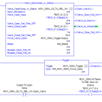
Ladder diagram (LD)
Ladder Diagram is a graphical programming language that is based on relay-based circuits, making it easy to understand and troubleshoot. The principle of operation of the basic elements, such as normally open and closed contacts, is identical to the electric components. This PLC programming language was designed to replicate the layout of the electrical drawings.
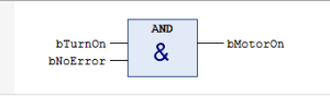
Function block diagram (FBD)
Function Block Diagram is a graphical programming language where a program is built upon blocks. The program layout is similar to logic gate systems. The visual editor is user-friendly and intuitive.
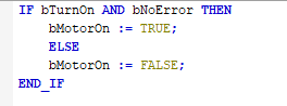
Structured text (ST)
Structured Text is a high-level PLC text programming language that closely resembles PASCAL. It has an advantage in some components of the graphical languages, code is being developed faster than in the graphical languages. For people who have experience with higher-level programming languages like C++, Structured Text offers a straightforward path into PLCs.
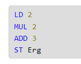
Instruction list (IL)
Instruction list is a low-level text language that is similar to Assembly language. As an example, there is no “IF” operation available in the predefined functions. In this language, each instruction begins in a new line.
Picture source:https://infosys.beckhoff.com/english.php?content=../content/1033/tcplccontrol/925244555.html&id=
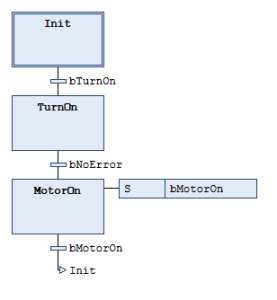
Sequential function chart (SFC)
The development of complex control sequences is made easier by the Sequential function chart graphical programming language. It consists of Steps and Transition conditions, which can easily mimic the sequence of operations as an example for a fixture. Transitions specify the circumstances that initiate the flow from one step to the next, Steps stand for particular processes or actions.
Some vendors have languages other than the ones listed above like Cause Effect Matrix (CEM) in the Siemens TIA Portal environment. Depending on the PLC brand and series some of the mentioned languages might not be available.
Well-known brands in the PLC Market
- Allen Bradley (Rockwell):
- Allen Bradley, under Rockwell Automation, is mostly known in the US market. Depending on the family of the particular PLC, different software might be required to program the device but the newest one is Studio 5000.
- Siemens:
- The market in Europe is where Siemens PLCs are primarily known. The TIA Portal software is used to program the latest Siemens PLCs.
- Twincat 3 Beckhoff:
- Beckhoff’s Twincat 3 PLCs are based on computer systems, which makes them different in terms of hardware approach from the other brands. They are programmed in Microsoft Visual Studio with some additional packages. The whole environment is called eXtended Automation Engineering (XAE)
These PLC brands are just a few examples among the well-known names in the field of Controls Automation Systems.