In the realm of industrial automation, where precision and reliability are paramount, the role of Programmable Logic Controllers (PLCs) is irreplaceable. PLCs are the backbone of automated systems, orchestrating processes in various critical industries. Ensuring the flawless performance of these PLCs is a mission-critical endeavor, and at the heart of this assurance lies the process of Factory Acceptance Testing (FAT) for control panels. In this exploration, we delve into the intricacies of FAT testing, understanding its nuances, and highlighting its pivotal role in the realm of industrial automation.
Unveiling the Essence of FAT Testing:
Factory Acceptance Testing is not merely a checkpoint in the production process; it is a meticulous evaluation conducted on PLC control panels before they embark on their journey to the industrial frontline. This process unfolds within the secure confines of the manufacturer’s facility, providing a controlled environment for the scrutiny and validation of the control panels.
At the crux of FAT testing is the pursuit of quality assurance. Imagine the control panel as the brain of an industrial operation, and FAT testing as the comprehensive health check it undergoes before entering the field. The sequence of operations, often presented in formats ranging from cause/effect tables to flow charts or logic diagrams, serves as the guiding script for the PLC/HMI program. This blueprint not only determines the high-level layout but also calls out specific field devices and control operations, influencing the logic executed within the control program.
FAT Testing for PLC Control Panels: Step-by-step instruction
In this step-by-step guide, we’ll navigate through the intricacies of executing a thorough FAT for PLC control panels, ensuring reliability and performance in industrial automation. You initially generated documents such as the IO list, electrical drawing, General Architecture (GA) of the panel, and Bill of Materials (BOM), which were then submitted to the customer for their approval. After that, a standard procedure for FAT Testing can be performed as follows:
Step 1: Define Testing Objectives and Criteria:
- Establish clear objectives for the FAT, aligning them with project specifications and requirements.
- Define acceptance criteria, including performance benchmarks, safety standards, and regulatory compliance.
Step 2: Assemble a Competent FAT Team:
- Form a team comprising control systems engineers, PLC/HMI programmers, and relevant stakeholders.
- Ensure that team members possess expertise in the specific industry standards and protocols applicable to the control system.
Step 3: Review Documentation:
- Thoroughly review project documentation, including the sequence of operations, mechanical layouts, and field device specifications.
- Cross-reference documentation with project requirements to ensure completeness.
Step 4: Simulate Real-World Scenarios:
- Develop test cases that simulate real-world scenarios the control system will encounter.
- Include edge cases and failure scenarios to validate the robustness of the system.
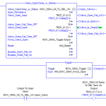
Step 5: Test Sequence Logic:
- Execute the sequence of operations outlined in the project documentation.
- Verify that the logic implemented in the PLC/HMI program aligns with the intended operations.
Step 6: Validate Communication Protocols:
- Test communication protocols between the PLC and other devices within the system.
- Ensure seamless data exchange and responsiveness between components.
Step 7: Assess Performance Under Load:
- Subject the control system to varying loads and stress tests.
- Evaluate the system’s performance under different operating conditions to identify potential bottlenecks.
Step 8: I/O Testing:
- Verify the input and output configurations against the specified field device requirements.
- Execute tests to confirm that the control system accurately responds to inputs and produces expected outputs.
Step 9: Safety System Testing:
- Test safety features and emergency shutdown systems.
- Ensure that the control system reacts appropriately to safety-critical scenarios.
Step 10: Documentation and Reporting:
- Document all test procedures, results, and observations.
- Prepare a comprehensive report highlighting any deviations from specifications and the actions taken to address them.
Step 11: Client Verification and Approval:
- Invite the client or end user to participate in the FAT.
- Present the results and seek client verification and approval of the control system’s performance.
Step 12: Implement Corrective Actions:
- Address any issues or deviations identified during the FAT Testing.
- Implement corrective actions in collaboration with the client to ensure compliance with project requirements.
Step 13: Final Client Acceptance:
- Obtain final client acceptance after corrective actions have been implemented.
- Confirm that the control system meets all specified criteria before proceeding to deployment.
Step 14: Documentation Archiving:
- Archive all documentation related to the FAT, including test procedures, results, and client approvals.
- Maintain a record for future reference and auditing purposes.
Considerations and Standards:
As with any intricate project, the devil resides in the details. Beyond the fundamental requirements lie considerations that are project-dependent. Specific industry standards, such as the IEC 61131 standard, may need adherence during hardware or software design. This standard, for instance, outlines specific architecture and programming standards for a PLC control program.
Some end users mandate control logic to be designed and implemented in a specific way to ensure consistency and standardization. From a hardware standpoint, certain projects may demand devices to be mounted in classified areas designated by OSHA as hazardous locations, necessitating specially rated hardware in those locations.